
The Atari Panther - Part 3 - Declared Features
Welcome back to this series of articles. In this third part we will review critically the declared features.
 |
| A 3D rendering of the Atari Panther. Author unknown. |
Articles:
- Part 1 - The history
- Part 2 - The hardware
- Part 3 - Declared features
- Part 4 - Deep dive
- Part 5 - Fun with object lists
Declared features
While the Panther was in development, Atari started a press campaign and communicated these features.
 |
| Features declared to the press (from Internet Archive) |
As usual in these cases, while true, some of these figures don’t quite represent the truth. Let’s see why.
‘7860 colors/screen’
This figure comes from the idea of changing all the 32 entries of the CLUT at every visible scanline. Indeed, in NTSC (including the over-scan area) there are 240 visible lines and a simple multiplication gives the expected result: 240 * 32 = 7860 colors.
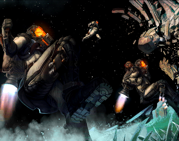
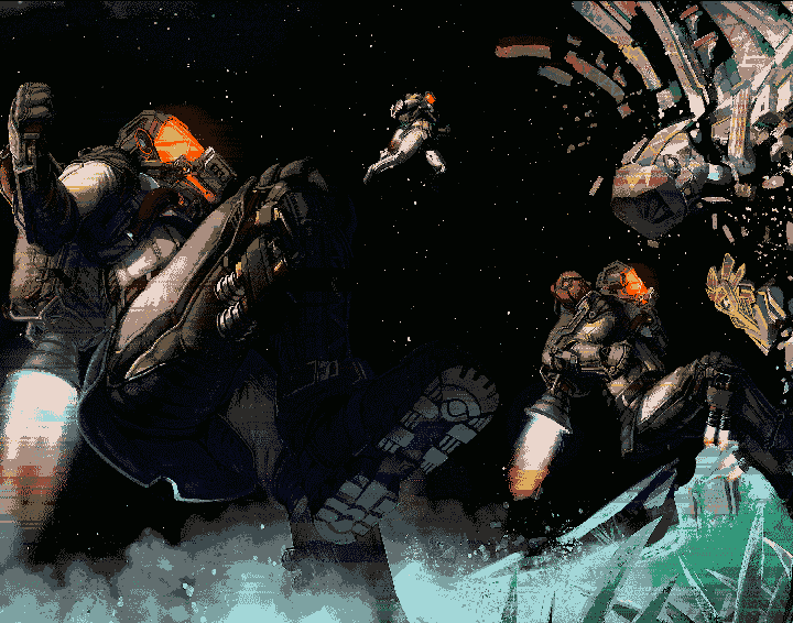
To have an idea of how effective this technique can be, take a look to the following image. It only 16 colors per scanline but the colors are modified across the screen.
 |
 |
|
| Amiga dynamic hires image. Source EAB | - | Same image without dynamic CLUT |
While doable and effective for static images, this technique becomes unrealistic for animated images that are typical on video games.
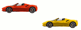
This can be explained with a simplified example. Let’s imagine a screen where a red car is positioned on the top half and a yellow one on the bottom half. The 32 colors palette contains both the reds and the yellows plus all the other needed colors. For example, the palette could contain 8 shades of red, 8 shades of yellow and 16 other colors.
 |
| Common CLUT |
Now a smart programmer decides to split the screen in two. On the top half a red ‘oriented’ palette of 32 colors is used. On the bottom half a yellow one is used. This allows for 16 shades of red on the top and 16 shades of yellow on the bottom.
 |
| Screen split in two and two optimized CLUTs. Notice the improved quality |
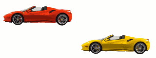
This is great, but what happens when the yellow car goes up and crosses the middle of the screen? The top of the yellow car becomes red because uses the upper palette.
 |
| Artifact |
This basic example shows that, if you don’t have full control on how the graphics move across the screen then it is extremely difficult to apply this technique.
It is possible to imagine a more elaborated setups and for sure the dynamic CLUT technique can improve colorfulness but, in any case, the advertised 7860 colors are not obtainable during actual game action.
‘Genlock option’
This is not implemented even if all seems ready for it.
A Genlock is a device that, when connected to a computer, allows to superimpose the graphic generated by the computer on top of another video source.
The Commodore Amiga and some MSX2 computers are some of the few home computers designed to work with a Genlock. Genlocks were also used in the arcades during the laserdisc era.
| Sega Astron Belt |
The computer/console has to be designed to work with a Genlock.
- First, the computer has to signal on a pin when a pixel is transparent. In this way, the Genlock knows when to show the other picture.
- Second, the two devices needs to have a common pixel clock. For this reason, the computer has an input pin where it can accept an external pixel clock.
The problem with the Panther is that the schematics of the dev kit show that while the needed pins are present at the video connector, they are not connected (see page 5 of the console schematics).
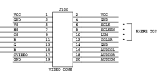 |
| Video connector (from the console schematics) |
Also the schematics of the GameShifter chip seems to prove this. The RGB DACs pixel clock is controlled by signal C2 (page 10 of the GS schematics). As visible at page 27, signal C2 in not connected to any pin. Indeed, signal C2 is generated inside the chip from the input pin SC and is synchronous to signal C1.
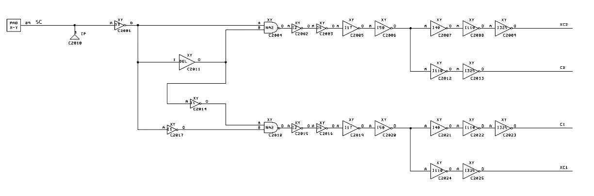 |
| Signal C2 generation |
Signal SC is the 16 MHz clock and, as consequence, there is no way to control it from a Genlock.
‘32 MHz, 32 bit object oriented, graphics processor’
It is true that the Panther has a 32 MHz crystal on the motherboard and a 32 bit data bus. Anyway:
-
some parts use only 16 bit
-
none of the parts run at 32MHz, some run at 16 MHz, some at 8 MHz or even 4 MHz
As usual, this is just marketing, bits and MHz are not indicative of the actual performance without looking at the whole architecture.
‘About 2000 sprites can be displayed simultaneously’
This figure may derive from the size of a Bitmap Object (BO) descriptor, which is 16 bytes long. As you may remember, a Bitmap Object is a sprite in the Panther jargon.
            31           24 23           16 15            8 7             0
            ----------------------------------------------------------------
long word 0 |type 0x01-0x7F| Y position    | Y size                |?|depth|
            ----------------------------------------------------------------
long word 1 | Y scale         | unused     | link                          |
            ----------------------------------------------------------------
long word 2 | data width      | drawn width        | X position            |
            ----------------------------------------------------------------
long word 3 | palette      | data address                                |R|
            ----------------------------------------------------------------
By filling all the available SRAM with BO descriptors, it is possible to store 32 * 1024 / 16 = 2048 BO descriptors.
But, can they be displayed?
Let’s start with a first experiment: to distribute uniformly all the BOs across the scanlines. On a NTSC system there are 200 lines. This means about 2048 / 200 = 10 BOs per line. Ten or eleven BOs per line is absolutely within the capabilities of the console. So, technically, ‘About 2000 sprites can be displayed simultaneously’ is a true statement but it tells nothing about the real capabilities. Indeed, the sprites are all 1 scanline tall and therefore quite useless.
Let’s try something more meaningful. We can use BOs large 16 x 16 pixels and put them in a grid. When the screen is full we start again creating a new layer. Horizontally we can fit 320/16 = 20 BOs. Vertically we can fit 200/16 ~= 13 BOs. This means 20*13 = 260 BOs per layer. Assuming to position 2000 BOs, we would create 2000/260 = 7.7 layers on screen. Is this possible?
Every Bitmap Object needs 12 mclks to be processed (6 SRAM accesses) and, for a 16 colors sprite, 4 mclks (1 ROM access) every 4 pixels fetched. In total, this is 12+4*4 = 28 mclks for each sprite on a given scanline.
mclks 0                 1    1    2    2    2
      0                 2    6    0    4    8
type  |SS|SS|SS|SS|SS|SS|RRRR|RRRR|RRRR|RRRR|
r/w   |rr|rr|rr|rr|ww|ww|rrrr|rrrr|rrrr|rrrr|

S = SRAM access
R = ROM access
On a scanline (64 us) there are about 64us * 16Mhz = 1024 mclks. Therefore the Panther can display about 1024/28 ~= 37 BOs per scanline (16 pixels wide in 16 colors). If we put them in a grid, as described above, we can create 37/20 ~= 1.8 layers or, in other words 37 * 13 = 481 BOs.
From this calculations It is evident that the hardware is far away from being capable of displaying 2000 ‘meaningful’ sprites.
‘Pixel programmable interrupt’
The Object Processor has an ‘instruction’ that can generate an interrupt for the CPU at a given scanline. Anyway, it is not possible to specify the x position. A more correct statement would have been “Scanline programmable interrupt”.
‘Fast hardware addition for object manipulation’
The Object Processor has an ‘instruction’ that allows to add a constant to the value present on a given memory address. While useful to create self-modifying Object lists, this hardly communicates a performance gain compared to the competition.
Closing
Thank you for reading up to this point ! In the next article we’ll continue to analyze what the Atari Panther can do.